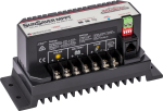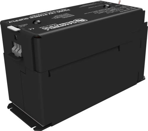
Manages voltage and amperage to protect battery


Overview
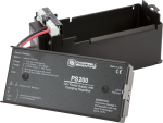
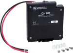
The PS200 is a 12-Vdc battery with a charge controller. The controller manages amperage and voltage for safe, optimized battery charging from a solar-panel or AC power source. It also measures various input, output, and status parameters to allow close monitoring of the battery during charging and use. The PS200 includes a 12-Vdc lead-acid battery, while the CH200 is for use with a user-supplied battery.
Note: If you do not need or desire the 6182 7 Ah Sealed Rechargeable Battery that is shipped with the PS200, consider ordering the 22238 instead.
Read MoreBenefits and Features
- Battery reversal protection
- Protects against high-amperage and high-voltage damage to power supply
- Ability to monitor both load and battery current
- Real-time measurements of charge input voltage, battery voltage, on-board temperature, battery current, and load current
- Two-step constant voltage charging and temperature compensation optimize battery charging and increase the battery’s life
- Allows simultaneous connection of two charging sources (e.g., solar panel, ac wall charger)
Images


3D/CAD Files:
Similar Products
Detailed Description
The PS200 power supply consists of a rechargeable, 7 A h, valve-regulated lead-acid (VRLA) battery and a charging regulator. This microcontroller-based smart charger has two-step constant voltage charging and temperature compensation that optimize battery charging and increase the battery’s life.
Two input terminals enable simultaneous connection of two charging sources. The PS200 also incorporates a maximum power point tracking algorithm for solar inputs that maximize available solar charging resources. RS-232 and SDI-12 terminals allow the PS200 to convey charging parameters to a datalogger.
The PS200 has several safety features intended to protect the charging source, battery, charger, and load devices. Both the SOLAR – G and CHARGE – CHARGE input terminals incorporate hardware current limits and polarity-reversal protection.
A fail-safe, self-resettable thermal fuse protects the CHARGE – CHARGE inputs in the event of a catastrophic AC/AC or AC/DC charging source failure. Another self-resettable thermal fuse protects the 12 V output terminals of the charger in the event of an output load fault.
The PS200 also has battery-reversal protection, and includes ESD and surge protection on all of its inputs and outputs.
Specifications
| Operational Temperature | -40° to +60°C (VRLA battery manufacturers state that “heat kills batteries” and recommend operating batteries at ≤ 50°C.) |
| Dimensions | 19 x 7.6 x 10.6 cm (7.5 x 3 x 4.2 in.) |
CHARGE - CHARGE Terminals (AC or DC Source) |
|
| AC | 18 to 24 VRMS (with 1.2 ARMS maximum) |
| DC | 16 to 40 Vdc (with 1.1 Adc maximum) |
SOLAR Terminals (Solar Panel or Other DC Source) |
|
| -NOTE- | Battery voltages below 8.7 V may result in less than 3.0 A current limit because of fold-back current limit. |
| Input Voltage Range | 15 to 40 Vdc |
| Maximum Charging Current | 4.0 Adc typical (3.2 to 4.9 Adc depending upon individual charger) |
Quiescent Current |
|
| No Charge Source Present | 300 μA maximum |
| No Battery Connected | 2 mA maximum |
Battery Charging |
|
| -NOTE- | Two-step temperature-compensated constant-voltage charging for valve-regulated lead-acid batteries; cycle and float charging voltage parameters are programmable with the default values listed. |
| CYCLE Charging | Vbatt(T) = 14.70 V - (24 mV) x (T-25°C) |
| FLOAT Charging | Vbatt(T) = 13.65 V - (18 mV) x (T-25°C) |
| Accuracy | ±1% (on charging voltage over -40° to +60°C) |
Power Out (+12 Terminals) |
|
| Voltage | Unregulated 12 V from battery |
| 4 A Self-Resettable Thermal Fuse Hold Current Limit |
|
Measurements |
|
| -NOTE- | At -40° to +60°C |
| Average Battery Voltage | ±(1% of reading + 15 mV) |
| Average Battery/Load Current Regulator Input Voltage |
±(2% of reading + 2 mA) Impulse type changes in current may have an average current error of ±(10% of reading + 2 mA). |
| Solar |
±(1% of reading - 0.25 V) / -(1% of reading + 1 V) 1.0 V negative offset is worst-case due to reversal protection diode on input; typical diode drop is 0.35 V. |
| Continuous |
±(1% of reading - 0.5 V) / -(1% of reading + 2 V) 2.0 V negative offset is worst-case due to two series diodes in AC full-bridge. Typical diode drops are 0.35 each for 0.7 V total. |
| Charger Temperature | ± 2°C |
Documents
Product Brochures
Downloads
PS200 Example Programs v.1.1 (36.4 KB) 08-12-2014
CR1000 programming examples for use with the PS200. The examples show how to use both SDI-12 and RS-232 advanced instruction programming techniques.
Frequently Asked Questions
Number of FAQs related to PS200: 5
Expand AllCollapse All

