This product is not available for new orders. We recommend ordering: CR1000Xe.

| Services Available | |
|---|---|
| Repair | Yes |
| Calibration | Yes |
Overview
The CR1000X is our flagship data logger that provides measurement and control for a wide variety of applications. Its reliability and ruggedness make it an excellent choice for remote environmental applications, including weather stations, mesonet systems, wind profiling, air quality monitoring, hydrological systems, water quality monitoring, and hydrometeorological stations.
The CR1000X is a low-powered device that measures sensors, drives direct communication and telecommunications, analyzes data, controls external devices, and stores data and programs in onboard, nonvolatile storage. The electronics are RF-shielded by a unique sealed, stainless-steel canister. A battery-backed clock assures accurate timekeeping. The onboard, BASIC-like programming language, common to all contemporary Campbell Scientific data loggers, supports data processing and analysis routines.
Read MoreBenefits and Features
- Operational in extreme environments with a standard operating range of -40° to +70°C and an extended operating range of -55° to +85°C
- Connects directly to a computer's USB port
- Captures quickly changing data values with fast analog measurement capabilities (300+ Hz)
- Differentiates even slight changes in data values with higher-resolution measurements (24 bit Adc)
- Includes two non-isolated current input channels for directly connecting sensors with 0-to-20 mA or 4-to-20 mA current outputs
- Contains an onboard CPI port for hosting Campbell high-speed sensors and distributed modules (CDM)
- Directly connects to Ethernet
- Includes microSD card drive for extended memory requirements
- Provides simple serial sensor integration and measurement with SDI-12, RS-232, and/or RS-485
- Supports full PakBus networking
- Includes embedded web page for direct connection via web browser
Images


3D/CAD Files:
Detailed Description
The CR1000X is a low-powered device designed to measure sensors, drive direct communication and telecommunications, analyze data, control external devices, and store data and programs in on-board, non-volatile storage. The electronics are RF-shielded and glitch-protected by a unique sealed, stainless-steel canister. A battery-backed clock assures accurate timekeeping. The on-board, BASIC-like programming language—common to all Campbell Scientific data loggers—supports data processing and analysis routines.
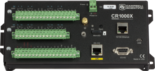
The CR1000X wiring panel includes two switchable 12 V terminals, analog grounds dispersed among 16 analog terminals, and unpluggable terminal blocks for quick deployment.
Compatibility
Please note: The following shows notable compatibility information. It is not a comprehensive list of all compatible products.
Measurement and Control
| Product | Compatible | Note |
|---|---|---|
| SDM-SIO2R |
Software
| Product | Compatible | Note |
|---|---|---|
| DevConfig | Version 2.16 or higher | |
| KonectGDS | ||
| LoggerLink | Version 1.6 or higher | |
| LoggerNet | Version 4.5 or higher | |
| LoggerNet Linux | Version 4.5 or higher | |
| PC200W (retired) | Version 4.5 or higher | |
| PC400 | Version 4.5 or higher | |
| RTDAQ | Version 1.3 or higher | |
| Short Cut | Version 4.0 or higher |
Additional Compatibility Information
Sensors
With several terminal types, the CR1000X is compatible with nearly every available sensor, including analog (both voltage and current), thermocouples, serial, SDI-12, pulse, and frequency sensors.
Measurement & Control Peripherals
The CR1000X is compatible with all our CDMs, multiplexers, vibrating-wire interfaces, terminal input modules, and relays.
Communications
The CR1000X communicates with a PC via direct USB port, 10/100baseT Ethernet port, multidrop modems, short-haul modems, phone modems (land line, digital cellular, and voice-synthesized), RF telemetry, and satellite transmitters (HDR GOES, Argos, Meteosat, Iridium, and Inmarsat).
Data can be viewed on the CR1000KD Keyboard Display, the CD100 Mountable Display with Keyboard, an iOS or Android device (requires our free LoggerLink app), CD295 DataView II Display, or other third-party devices.
Enclosures
The CR1000X and its power supply can be housed in any of our standard enclosures.
Power
Any external 12 Vdc source can power the CR1000X datalogger. Campbell Scientific power supplies commonly used with the CR1000X are the BPALK, PS150, and PS200.
Software
Campbell Scientific proprietary software is required to program, configure, and communicate with the CR1000X datalogger. Various software options are available to meet a breadth of application needs. At a minimum, Short Cut and PC200W are needed. Consult with a Campbell Scientific Support and Implementation Engineer to determine the best software option.
Specifications
| -NOTE- | Additional specifications are listed in the CR1000X Specifications Sheet. |
| Operating Temperature Range |
|
| Maximum Scan Rate | 1000 Hz |
| Case Material | Anodized aluminum |
| Analog Inputs | 16 single-ended or 8 differential (individually configured). Two analog inputs can measure 4 to 20 mA or 0 to 20 mA natively. Four analog inputs can provide pulse/digital I/O functions. |
| Pulse Counters | 10 (P1 to P2 and C1 to C8) |
| Voltage Excitation Terminals | 4 (VX1 to VX4) |
| Maximum Source/Sink Current |
|
| Communications Ports |
|
| Data Storage Ports | microSD |
| Switched 12 Volt | 2 terminals |
| Digital I/O | 8 terminals (C1 to C8) configurable for digital input and output. Includes status high/low, pulse width modulation, external interrupt, edge timing, switch closure pulse counting, high-frequency pulse counting, UART, RS-232, RS-485, SDM, SDI-12, I2C, and SPI function. Terminals are configurable in pairs for 5 V or 3.3 V logic for some functions. |
| Input Limits | ±5 V |
| Analog Voltage Accuracy |
|
| ADC | 24-bit |
| Power Requirements | 10 to 18 Vdc input (See manual for further details.) |
| Real-Time Clock Accuracy | ±3 min. per year (Optional GPS correction to ±10 µs) |
| Internet Protocols | Ethernet, PPP, RNDIS, ICMP/Ping, Auto-IP (APIPA), IPv4, IPv6, UDP, TCP, TLS (v1.2), DNS, DHCP, SLAAC, Telnet, HTTP(S), SFTP, FTP(S), POP3/TLS, NTP, SMTP/TLS, SNMPv3, CS I/O IP, MQTT |
| Communications Protocols | CPI, PakBus, SDM, SDI-12, Modbus, TCP, DNP3, UDP, NTCIP, NMEA 0183, I2C, SPI, and others |
| Battery-backed SRAM for CPU Usage & Final Storage | 4 MB |
| Data Storage | 4 MB SRAM + 72 MB flash (Storage expansion of up to 16 GB with removable microSD flash memory card.) |
| Idle Current Drain, Average | < 1 mA (@ 12 Vdc) |
| Active Current Drain, Average |
|
| Dimensions |
23.8 x 10.1 x 6.2 cm (9.4 x 4.0 x 2.4 in.) Additional clearance required for cables and leads. |
| Weight | 0.86 kg (1.9 lb) |
Videos & Tutorials
Downloads
CR1000X Web Browser Interface v.1.2 (970 KB) 13-09-2024
Standard Datalogger Web Browser Interface
Use this download to update the data logger's web browser interface.
To install this file, send it to the data logger using file control found in the Device Configuration Utility or file control found in LoggerNet.
This interface is recommended for fast IP interfaces like Ethernet and Wi-Fi. It does NOT perform well over slow communications mediums like cellular.
Note: This is NOT for system data loggers that have custom interfaces like the SunSentry, Hydro-Link, Alert205, and MeteoPV.
Custom Menu Example Program for Connections Video v.1 (1 KB) 26-03-2024
This program demonstrates creating a custom menu for data logger displays and corresponds to the Campbell Connections video: Creating Custom Menus in CRBasic for a Data Logger Display.
Data Logger Wiring Excel Template (1 KB) 26-03-2024
This is a data logger wiring diagram spreadsheet template that accompanies the Wiring Diagram Video. The spreadsheet includes templates for CR6, CR1000X, CR300, CR310, and CR350 data loggers. The file is an Excel template and works best with Microsoft Excel.
Frequently Asked Questions
Number of FAQs related to CR1000X: 8
Expand AllCollapse All
-
If a CPI-enabled device is running and there are skipped scans in the data logger, what can be done?
The default CPI bus speed setting is 250 kB/s. The speed is adjustable in your CRBasic data logger program. Use the CPISpeed() instruction in your CRBasic program to adjust the CPI bus bandwidth to meet the following maximum combined (total) Ethernet cable lengths:
- 1000 kB/s for maximum combined Ethernet cable lengths of 15.2 m (50.0 ft)
- 500 kB/s for maximum combined Ethernet cable lengths of 61.0 m (200.0 ft)
- 250 kB/s for maximum combined Ethernet cable lengths of 152.4 m (500.0 ft)
-
Return the CR1000X to Campbell Scientific for repair. For assistance obtaining a Return Material Authorization (RMA), follow the instructions on the Repair and Calibration page.
-
The potential transformer and the current transformer provide differential outputs that have galvanic isolation from the voltage and current in the circuit they are measuring. However, there is no need to run the outputs of these transformers into differential inputs of the data logger and unnecessarily consume additional data logger channels. We conducted extensive testing for noise immunity, for inaccuracies from ground loops, and more before concluding that single-ended measurements in the ACPower() instruction have the same performance as differential measurements would provide. Please note that as a result of the galvanic isolation of the potential transformer and current transformer, the data logger ground is NOT connected to the ground of the circuit they are measuring.
Said differently, you can connect differential outputs of a sensor to single-ended inputs of the data logger. However, doing so creates the possibility of poor common-mode noise rejection in the data logger and the possibility of introducing inaccuracies from ground loops between the sensor and the data logger. Note that in this application, the transformer isolation of the potential transformer and the current transformer eliminates these concerns.
Simply connect one of the potential transformer secondary wires and one of the current transformer secondary wires to the data logger ground. Which wire in either case makes a difference, as the phase information allows the measurement of power flowing in either direction. If you measure negative real power when it should be positive, then reverse the secondary wires of the potential transformer where they connect to the data logger. Alternatively, you can reverse the secondary wires on the current transformer, but don't reverse both pairs of wires.
-
The CR1000 and CR1000X will be sold concurrently for no less than two years. We anticipate the CR1000 will be retired in December of 2019 and will be supported until December of 2029.
-
When idle, the CR1000, CR6, and CR1000X consume less than 1 mA @ 12Vdc. Similar to the CR6, the CR1000X has a much faster processor that requires more power when up and running. As such, there will be higher current draws during active measurements, serial communications, or when plugged into a PC via USB or Ethernet.
It may be helpful to think of the CR6 and CR1000X as being built on the same "platform."
-
Although there are significant additions to the CR1000X program instructions that are not available in the CR1000, in most cases, you can load your program written for the CR1000 to a CR1000X with minor instruction changes. The most notable of the minor instruction changes is in the analog measurement instructions. For more information, see the "Replacing Your CR1000 Data Logger with a CR1000X: What You Should Know" blog article.
Casos de estudio
Overview In the heart of the UAE’s Empty Quarter desert—one of the harshest and least hospitable......read more
Overview The Udhampur-Srinagar-Baramulla Rail Link (USBRL) project is of national importance as it connects Kashmir to the......read more
In 2022, as Hurricane Fiona unleashed relentless rain on Puerto Rico, the Puerto Rico Landslide......read more
Background Manitouwadge Municipal Airport is located 48 km (29.8 mi) north of highway 17 on Highway......read more
The Homestake Neutrino Experiment—also referred to as the “Davis Experiment” after physicist Ray Davis, who......read more
Overview In May 2019, the Government of Zambia embarked on the Climate Adaptation Water and Energy......read more
Overview As part of the United Nations Development Programme's (UNDP) Climate Adaptation Water and Energy Programme......read more


